Marking Technology


Marking devices and equipment for permanent marking of characters and data matrix codes

The company Systemforschung supplies a wide range of marking machines for the steel and metal processing industry. In addition to standardized marking systems such as our hand-held needle/ dot pin markers, we develop customized marking solutions for your application. For this purpose, we rely on extensive construction kits with proven assembly groups and components. Especially in the field of steel mills, rolling mills and tube mills, solid and proven technologies are in demand due to the harsh environment. Needle embossing technology offers further advantages over “stamping” with conventional machines. In addition to “needle embossing technology”, we supply “scribe markers” as well as conventional daisy wheel stamping machines for various applications.

The Close-Close Loop technology is available for almost all machines and tools that can be controlled with the LUCy G Controller and the LUCy G2.0 software.


Software and Visualization

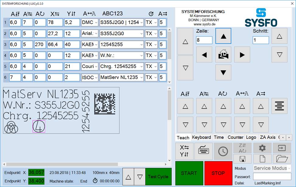
The new PC-based marking controller LUCy is the control basis for all marking machines and is capable of controlling up to four axes (X,Y,Z,A) simultaneously. The marking controller can be used as a desktop controller or for control cabinet mounting, and is combined in a space-saving housing. It has a 10.1″ touch display for visualization. Interfaces: 1x RJ45, 2x USB ports for keyboard, mouse or barcode scanner, HDMI.

The marking programs are created and managed with the LUCy G2.0 software. When creating the marking layout, you always keep an eye on the essentials. The LUCy G2.0 software creates G-Code files (DIN 66025/ISO 6983) based on preset parameters and variables. The lines and arcs of individual characters are scaled, transformed and rotated using mathematical calculations. The resulting values are displayed as graphics in the software interface (marker preview) and used to create G-Code files. Additionally, modules for an automated generation of marker texts have been integrated. The software is network-compatible and can interact as master/slave.

The standard software has the following functions
  • Different fonts ( Standard: ISO, Arial, Arial Narrow, Courier, DIN)
  • LT Forms offers 80 special shapes e.g. frames, CE signs, earthing signs...
  • Logos and emblems
  • DMC in standard up to 24x24 points
  • Font height scalable in 0.1mm increments
  • Character spacing in 0.1mm increments scalable
  • X, Y, Z and a axes Displacement
  • Line rotation
  • Marking speeds
  • Extensive, parameterizable time, day, date and shift settings
  • Parameterizable counter functions
  • Password functions for different user authorizations
  • Z and A axis functions
  • Teach functions (with approach to start position)
  • Drag+Drop (with approach to start position)
  • Active text field calculation
  • Test drive
  • Automatic saving of the executed marker file
  • Automatic saving of the executed marking as PNG file as 1:1 image
  • Selection of the start mask (automatic loading of the set mask)
  • Open, save marker files
  • Different customizable language and color options
  • ZOOM function (visualization)
  • Selection of different marking areas
  • Languages: German, English, French, Italian, Russian, Hungarian, Turkish
  • G-Code output to file
  • Simple control and integration into a PC network (multi-user capability in slave/master operation)
Typical users of this procedure are
  • Steel, forging and tube mills
  • Rolling and ring rolling mills
  • Steel processing and trade
  • Automotive and commercial vehicle industry
  • Rolling stock
  • Steel and mechanical engineering
  • Aerospace
Advantages of needle and scoring embossing technology

The stroke of the marking needle also compensates for large surface tolerances of 4-5mm, as is usual with flame cuts, for example. A further advantage is that the scale layer flakes off and cannot settle in the closed engravings of the punches. This improves the automatic reading capability of our automatic OCR character recognition systems. The maximum surface hardness of the material to be marked is approx. 58 HrC, depending on the material.

Development of special tools
Embossing unit motor adjustable, automotive industry

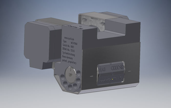
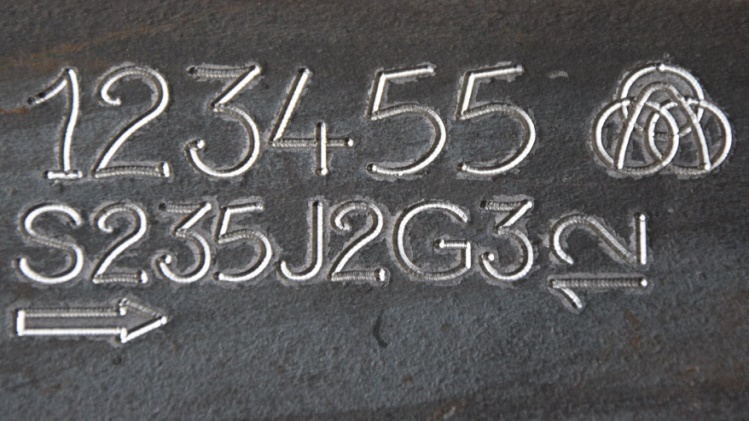
The components to be marked are positioned in an embossing press using robots in a hot forming system. In three steps, the embossing plant embosses the manufacturer’s symbol and the supplier code, part number and revision status and the production date in less than 3 seconds. Depending on the version, data matrix codes can be marked via the free X and Y axes. The engravings are designed in such a way that they do not damage the applied aluminium oxide layer.

The selection and positions of the wheels are monitored by incremental encoders. For this purpose, the specially developed “Close-Close Loop” method is used, in which the control system compares steps and step losses and readjusts steps if necessary. If the desired positions can no longer be reached, the controller goes into alarm or malfunction mode before the marking test.

Application examples
Marking of billets and slabs in steel works

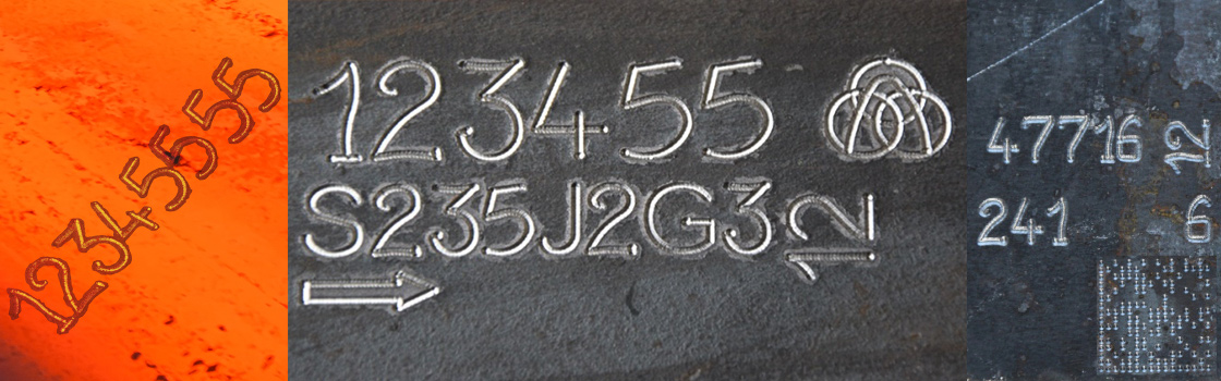
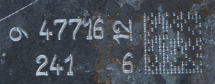
On the flame-cut surface of billets (marking temperature approx. 900°C), the batch number is stamped as plain text and a data matrix code using a needle marker. Marking takes place directly on the first station of the reversible cooling bed to avoid mix-ups. The markings are then read and verified with an OCR reading system. In the subsequent production steps (wire drawing, rolling mill), the marking is used for alloy or batch allocation. punch reading.

Marking of sheet metal blanks with a needle/dot pin marker

Component, material and manufacturer symbols marked on the upper side of a shaped blank (flame-cut blank). In subsequent process steps, the parts are deburred, sandblasted and coated with a primer. The font is a special font (SYSFont), which can be identified even if the characters are only partially present.

Marking of material samples in a sample workshop

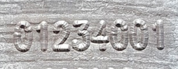
In the first step, the material samples supplied by the steelworks are marked at different positions before processing (saw cutting). From these, so-called “test specimens” (tensile torsion specimens) are produced in subsequent production steps. The markes numbers are marked with the font SysFont and are identifiable even if a part of the marking is missing or lost.

Marking of drawn hydraulic tubes

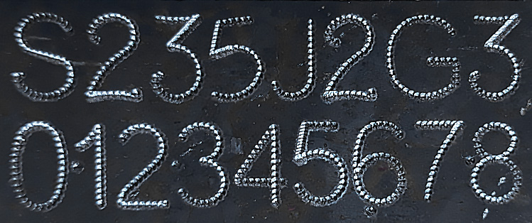
The markers show the difference between a marker in continuous vibration mode and a dotted marker. Both markings correspond to the so-called standard for pressure vessels (DIN, ASME, and AISI) in the “Low Stress” range (lowest notch effect), since the points were introduced into the component surface by means of a rounded needle. Due to its chemical composition, the needle does not produce any contact corrosion.

The mechanical construction kit for needle embossers has 4 assemblies

X40

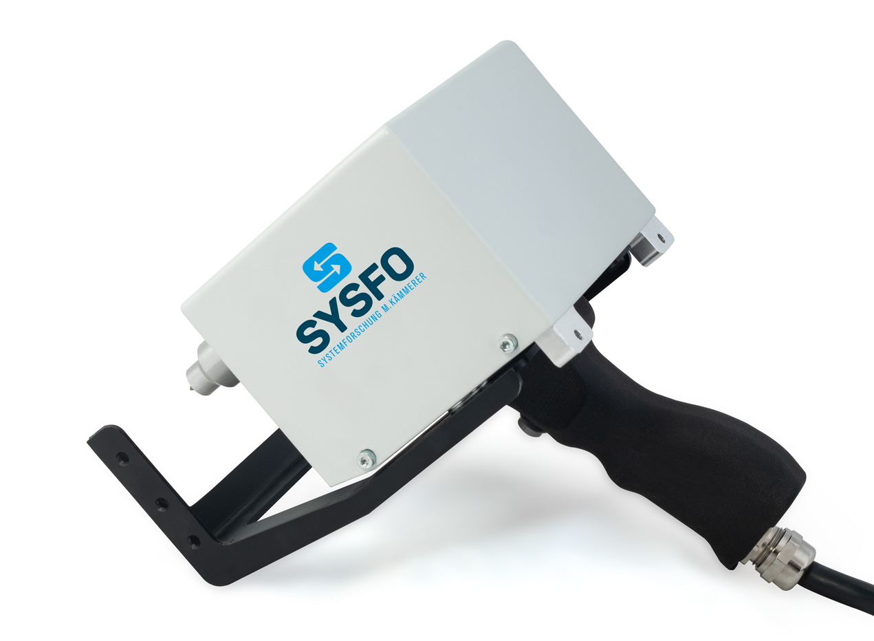
Small, very fast, universally applicable marking units.
Versions: Mobile device, integration, table machine

Marking range: 50x40mm, 100x40mm, 150x40mm

Marking speed: up to 12 characters/sec*.

Dimensions (Integration Model) from: 105x180x105mm [bxhxt]

Weight (Integration Model): 1.7kg, 2.2kg, 2.7kg

Marking cylinder: V12/75, V16/75, V22/75

Marking depth: 0,05 -0,5mm (steel with a tensile strength of 520N/mm²)

X100

Universal marking units with medium working range.
Versions: Mobile device, integration, table machine

Marking range: 150×100, 250x100mm

Marking speed: up to 12 characters/sec.*

Dimensions (Integration Model):

Weight (Integration Model): 9.7kg; 10.5kg

Marking cylinder: V12/75, V16/75, V22/75, V36/110

Marking depth: 0,05 -1,00mm (steel with a tensile strength of 520N/mm²)


X200

Universal marking units with large working range.
Versions: Mobile device, integration, table machine

Marking area: 250×200, 300x200mm

Marking speed: up to 12 characters/sec*.

Dimensions (Integration Model):

Weight (Integration Model): 13.7kg; 15.5kg

Marking cylinder: V12/75, V16/75, V22/75, V36/110

Marking depth: 0,05 -0,70mm (steel with a tensile strength of 520N/mm²)


XHD

Strong needle embosser for marking hot steel mill products with extreme penetration depths.
Available as integration and table machine.

Marking range: 50x100mm, 70x150mm

Marking speed: up to 12 characters/sec.*

Dimensions (Integration Model): 245x330x170mm [bxhxt]

Dimensions (high temperature model): 390x360x225mm [bxhxt] Incl. heat protection housing

Weight (Integration Model): 17.0 kg; 19.5 kg

Marking cylinder: V36/150

Marking depth: 0,05 -1,50mm (steel with a tensile strength of 520N/mm²) / 1,00 -1,50mm (steel at a temperature>900°C)


Integration into systems and IT structures

In addition to software integration into existing structures, we also offer the planning of hardware components in your plant ,( bridge constructions and industrial robots). Thus we are able to offer you an overall concept from the development to the turnkey plant.

The communication possibilities of the control system (in string format) can be adapted by us in terms of software technology. All functionalities of the control can be used and addressed when communicating with external controls. For this we differentiate in the communication protocol between single set/function or line set. Thus, not only text contents but also positions, font heights and other parameters can be transmitted to the control system as required.

The structure of the communication is deliberately simple and a command set consists of:

  • Action; line; value.
  • The controller responds to each command set with an “echo”
  • Action; Line; Value; ACK/NACK.

The following standard communication options are available for integration into the higher-level plant control system (process control system):

  • TCP/IP
  • Hardware signals (Start, Stop, Ready, Ready, Marked)
  • Communication in bus and net topology can take place via so-called interface converters.
  • ProfiBus
  • ProfiNet
  • Serial communication (RS232)

We archive the marking data and images in your database using the following database systems, among others:

  • Oracle
  • SQL
  • MySQL
Marking Technology
PDF DOWNLOAD