Automatic Measurement


contactless determination of 3D surface models in the production line
lengths, diameter, roundness, cylindricity, contour shape, volume

BACKGROUND AND OBJECTIVES

Continuous efficient 100% quality control is still a major challenge in many industries, and it is becoming more and more important in terms of complete documentation and reliable quality assurance.

Systemforschung offers contactless measuring systems that monitor and document compliance with manufacturing dimensions and tolerances directly in the production line.

One example is the automatic measurement of railroad wheels directly in the production line. Axles and complete wheel sets can also be tested in the same way, even when they are hot.

REQUIREMENTS

Measurement of different types of railroad wheels, from streetcars to freight trains and high-speed trains. Measurements are taken in the test line for 100% hardness testing, ultrasonic and surface inspection.

  • Wheel diameter: 700 - 1350 mm
  • Hub length: 150-250mm
  • Weight: 200 - 800 kg
  • Cycle time: 72 seconds
  • Accuracy ±0,05mm
  • Measurements: Diameter, lengths, radii, thicknesses, runout, cylindricity, radial runout, lateral runout, contour shape.
  • Resolution: up to 120 profiles per full rotation
  • Hall temperature: 0° - 35°C
  • Space requirement: < 3m in the test line
  • 100% documentation as printout
  • Permanent archiving in a database for traceability and statistical evaluation
SOLUTION CONCEPT

Mechanical design

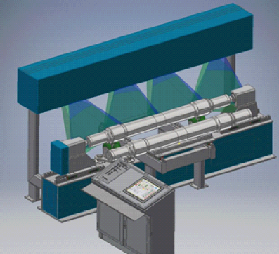
The chain conveyor of the test line is covered by a measuring chamber, to protect the measuring equipment from external dust, temperature and light influences. Inlet and outlet openings are protected with strip doors. In the test chamber, a hydraulic cylinder with chuck lifts out the wheel lying on the chain conveyor and rotates it 360° around the wheel axis.

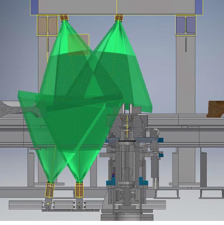
During the rotation, 4 high-resolution 3D laser scanners record a solid model of the surface. This measurement is repeated in a second rotation with an offset chuck so that the gripper positions do not leave any uninspected areas. The wheel is then lowered back onto the chain conveyor and released for further transport.

Measuring system, integrated in the test line, drawn without protective chamber.
Air conditioning

The cabin is equipped with thermal insulation and a 2-way climate system to keep the internal temperature constant. The appropriate air routing ensures that the inlet and outlet openings only have a limited effect on the temperature balance. In addition, the temperature of the test material is detected via infrared sensors.

Side view: View perspectives of the cameras (outlined in green) and hydraulic rotary cylinder with chuck.
Air conditioning

The cabin is equipped with thermal insulation and a 2-way climate system to keep the internal temperature constant. The appropriate air routing ensures that the inlet and outlet openings only have a limited effect on the temperature balance. In addition, the temperature of the test material is detected via infrared sensors.

Test sequence

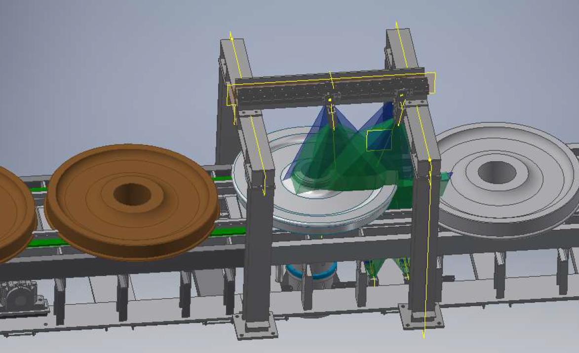
Before the test begins, the system receives the wheel type and the enable signal from the higher-level control of the test line when the test specimen is in position. The wheel is then lifted out of the chain conveyor, rotated and the angle tracked by a rotary encoder. The wheel is then lowered onto the conveyor, the chuck is rotated by 60° and in a second run the previously hidden areas of the underside are now visible.

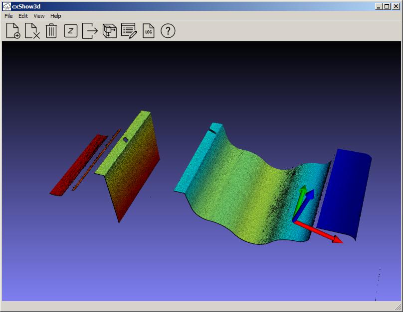
During the 360° rotation, each camera generates a 3D model from approx. 3000 scans of the unwound surface from its perspective. The data are sufficient to effectively reduce the unavoidable measurement noise so that valid measurements on the model are possible. The cameras are aligned in such a way that, for each wheel size, all areas of the cross section are captured by at least one camera with a favorable viewing angle.

View into the chamber during the measuring process. The laser lines of the individual cameras scan the surface in rapid alternation during the rotation.

These models from 4 perspectives are transformed into a common coordinate system, so that in this 3D wheel model any measurements can be evaluated, also to the 180° opposite side.

Unwinding of the wheel surface as seen from one of the four perspectives.

These models from 4 perspectives are transformed into a common coordinate system, so that in this 3D wheel model any measurements can be evaluated, also to the 180° opposite side.

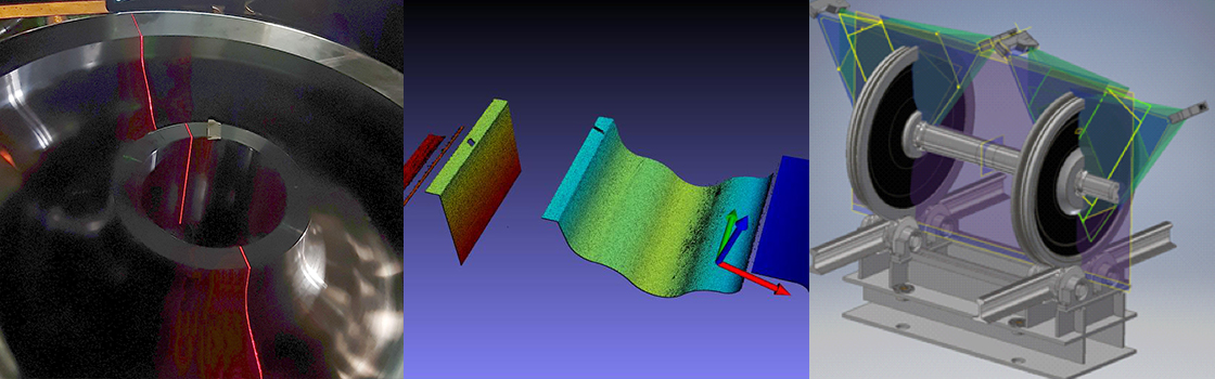
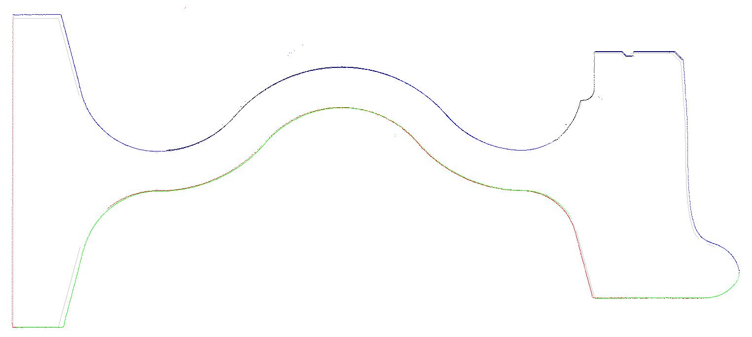
Section through a wheel side after the first turning process. The drawing is highlighted in gray and the measuring points from four perspectives are superimposed in different colors. You can see that the wheel still has oversize, as material is still required for the subsequent fine machining.

PLANT OPERATION

Communication, IT integration

The inspection system automatically learns the wheel type from the inspection line control system and can access the stored drawing data and measurement specifications. The measurement process is fully automated, the measurement specifications are evaluated and documented in a database.

The HMI (human machine interface) allows the user to access the measuring system and its parameters in different password-protected areas.

This Software consists of three main components:

  • WheelMeasControl is responsible for the flow control of the measuring process
  • WheelDataResearchCenter allows access to all measured data and statistics
  • WheelMPCreator allows comfortable setup of new wheel types

The Software is ready to install on WIN7 and Win10 PC (OS WIN7, WIN10 supported)

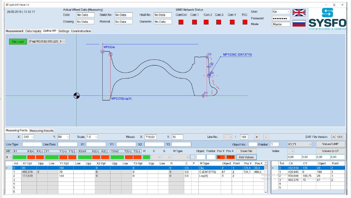
In the WheelDataResearchCenter overviews in tabular form, statistical evaluations and sectional views can be retrieved on the terminal and are available as printouts for retrieval. All data is stored on a central database server and compared with data from an existing material flow system and integrated into it. This means that statistics are also available on specific shifts, batches, and customers, so that transparency can be created at any time about the quality in the production process and weak points in production can be quickly detected.

Setup of a new wheel type on the terminal. The operator specifies each measuring specification by selecting drawing elements from the component drawing displayed above by mouse click.

Operation and setup

A measurement specification must be stored once for each wheel type. For this purpose, Systemforschung provides an intuitive configuration software, the WheelMPCreator. In the DXF drawing view, the individual measurement specifications can be linked to the corresponding contour elements with a mouse click. Together with the tolerances, the specifications are archived in a list along with the drawing.

Each measuring specification generates a line in the overview table during the measuring process, from which the adherence to the tolerances, the extremes of the deviation with angle position, mean value and standard deviation can be seen. The measured value progression over the angular position can also be displayed, as well as the individual sectional views.


Calibration

As with any high-quality measuring system, calibration must be carried out regularly. For this purpose, there is a precisely measured calibration body, which is moved into the system instead of a wheel, and a calibration program, with which a series of measurements are carried out with it. The software then automatically optimizes the setting parameters of the system so that the best possible measuring accuracy is achieved.

AXIS MEASUREMENT

The light-section method allows reliable, precise depth measurements and contour checks by mathematical evaluation of the image data’s. This non-contact optical measurement system (laser triangulation) also is used for a high-resolution 3D axis inspection.

Axle Measuring Station with pneumatic positioning table and on-site control panel (without protection housing)

The required positioning accuracy is only approximately +-50 mm in X and Y Axis at pneumatic feeding table (application site).

Two adjustable positioning prisms made of POM serve for safe support of the axle in to lifting unit.

As soon the mesuring Cycle ist started (by opperator or conveyor line’s PLC) the pneumatic feeding table transports the axle into the lifting position of the prism roller unit. The prism roller unit is dirven by screw.

This allows to position the axle in Z-direction with a accuracy of 0 /-0.05mm under exact Z- level. Now the two turning supports (driven by hydraulic cylinder) clamp the axle in central position . Now the measurin cycle starts while the axis rotates slowly.

Measuring results and the actual „Status“ of the Measuring-System, here visualization for wheels

The required positioning accuracy is only approximately +-50 mm in X and Y Axis at pneumatic feeding table (application site).

Two adjustable positioning prisms made of POM serve for safe support of the axle in to lifting unit.

As soon the mesuring Cycle ist started (by opperator or conveyor line’s PLC) the pneumatic feeding table transports the axle into the lifting position of the prism roller unit. The prism roller unit is dirven by screw.

This allows to position the axle in Z-direction with a accuracy of 0 /-0.05mm under exact Z- level. Now the two turning supports (driven by hydraulic cylinder) clamp the axle in central position . Now the measurin cycle starts while the axis rotates slowly.

MEASUREMENT OF COMPLETE WHEEL SETS

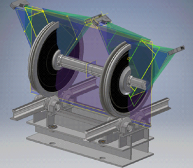
Furthermore the laser triangulation technology is able to evaluate complete assembled wheel sets in a roller prism.

Mit einer niedrigeren Kameraposition ist es auch möglich, Radsätze zu untersuchen, die in einem Eisenbahnwagen montiert sind. Insbesondere der Verschleiß der Lauffläche kann auf diese Weise überwacht werden.

For both wheels, synchronism, cylindricity, radial runout, lateral runout and  contour shape are evaluated within one rotation.

With a lower camera position it will also be possible to supervise wheel sets munted in a railroad car. Especially the wear of the tread can be monitored in this way.

Measuring complete wheel sets
CONCLUSION

With modern non-contact optical measuring methods, 100% inspection for dimensional accuracy is possible directly in the test line. In the event of quality problems, feedback is provided promptly and the dimensional accuracy is documented and traceable over the entire production quantity. Time-consuming sampling from the process is no longer necessary.

Wheel Measurement
PDF DOWNLOAD