Automatic Measurement

Measurements are made in almost every area. What unites them is that they should be as accurate as possible. Usually it is about the correct dimensions of a product or the adherence to previously agreed tolerances. Industrial cameras and intelligent evaluation algorithms support you reliably and precisely in the areas of profile control, tolerance testing or linearity testing. No matter whether profile shape, shaping, contour, position or dimensional accuracy – we know what matters when it really has to be accurate.

Application examples
  • Profiles, long and round products of the steel industry
  • Railway wheels, axles
  • Rims, brake discs
  • Reeds
  • Wire and sheet coils

The following values can be measured with the automatic optical measurement and the “SysfoAutoMeasure” software when the component is viewed from above. When measuring e.g. rotationally symmetrical parts or components that are measured during rotation, the optical measurement can also be used to measure and determine shape and running tolerances such as cylindrical shape, roundness, coaxiality, concentricity and axial runout.

An additional possibility of testing is the comparison of a theoretically optimal contour with the processed height image. After aligning the workpiece, two geometric models (e.g. from a DXF file) are loaded, representing the tolerances of the component. Subsequently, the height image is compared with the geometric model, similar to a template or gauge.

Example: Automatic measurement of release bolts

In the following example 8 measuring points (MP01- MP08) and two center points (CP00- CP01) are used. The measuring points are linked with the center points and the measuring method. The dimensions are given as the theoretically optimum value and the permissible dimensions. By additionally linking the measured values (measuring points), form/position tolerances can be generated from the measured values.

For the measurement of the component, a so-called height image with a projected laser line is recorded by means of laser triangulation. For this purpose, either the component or the camera is moved at a specified speed. The first step of the evaluation is to align the height image of the component, this is done by mathematical calculation of the reference values to the defined center points. After completion of the image processing with subsequent image evaluation, the values of the measuring points are output (UI) and saved. The measured values are automatically compared with the theoretically optimal value and the tolerated deviations. With complex contours, it is possible to load a second contour (e.g. DXF file) and compare this contour with the image. The software decides based on the criteria (tolerated allowance) whether the component is ACK or NACK.

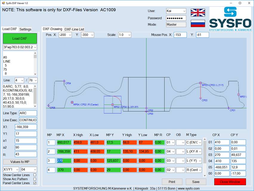
Software for creating test programs using DXF contours SysfoDXFViewer. The following PC software is used to create and manage test programs. A specified DXF contour of the component to be measured is created and saved in a common CAD program (e.g. AutoCad, Solid Edge). The DXF is loaded by the software SysfoDXFViewer and displayed on the screen. The operator can then scroll through the individual lines of the DXF drawing and assign various measuring and center points. A direct transfer of the line end or center points into the measuring or center points is possible. 35 measuring points and 5 center points are available as standard. After completion of the settings, the set values including all test relevant data are saved. For documentation purposes, the set values and test procedures can be output and printed as a PDF document. The data can be displayed, changed and managed at any time with the software SysfoDXFViewer.

Exemplary representation: “Contour measurement for track wheels” user interface

Exemplary representation: “Contour measurement for track wheels” user interface