Laser triangulation (light section method)

In laser triangulation, a line is projected onto the component surface with a special line laser. Using a high-resolution 3D camera, the height profiles of the object are now recorded line by line in motion. The recording frequency determines the resolution (scans/mm). Subsequently, the collected image material is filtered by software, compared with specifications and automatically evaluated. The light section method allows reliable, precise depth measurements and contour checks through mathematical evaluation of the image data.

The blue laser line shows the position at which the sheet surface is scanned as it passes through. Cracks, roll-ins, shells and dents are thus detected and precisely measured.

The blue laser line shows the position at which the sheet surface is scanned as it passes through. Cracks, roll-ins, shells and dents are thus detected and precisely measured.

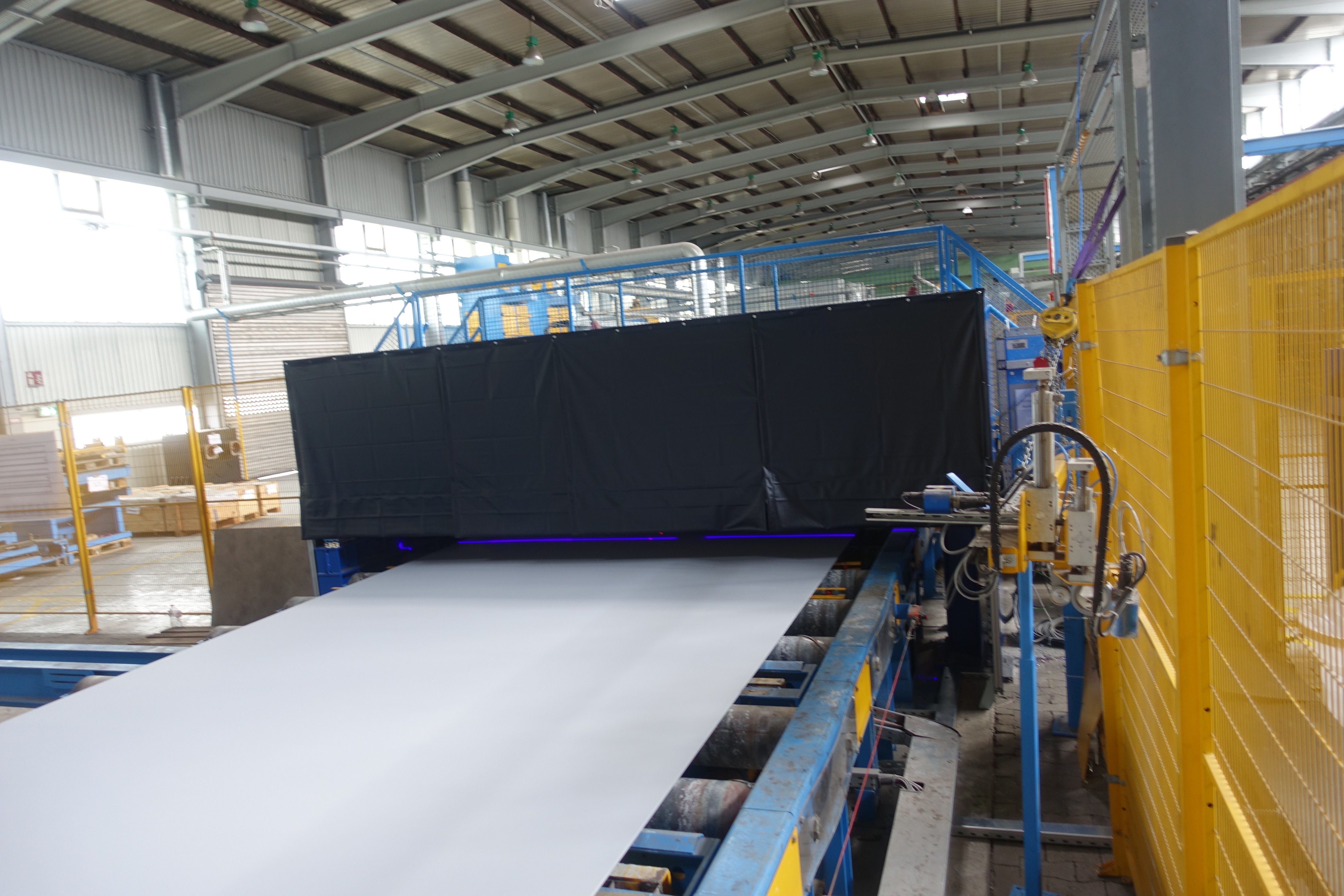
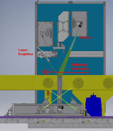
Side view: The camera creates 1000 3D profiles per second while passing through.
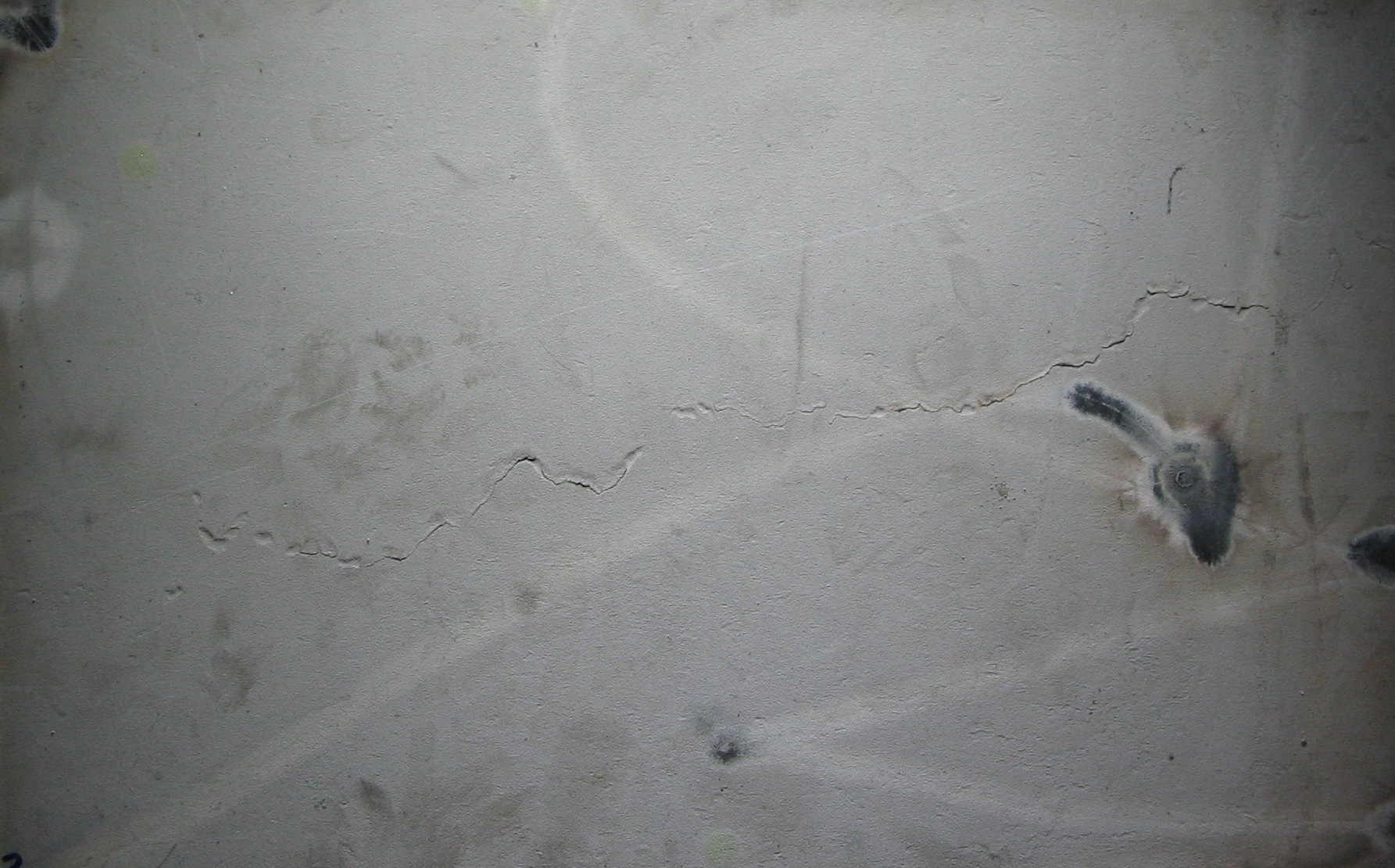
Detail photo of the sheet metal surface: The crack can be seen here by the shadow cast and by reflections on the lower edge. In addition, there are many discolorations.

Detail photo of the sheet metal surface: The crack can be seen here by the shadow cast and by reflections on the lower edge. In addition, there are many discolorations.

Evaluated 3D image

Grey: sheet level
White: at least 0.15mm raised
Black: at least 0,15mm deepened

The discolorations have no influence on the 3D image.

CVS profile analysis
PDF DOWNLOAD
This page as PDF
PDF DOWNLOAD